I am currently investigating stress
transmission inside complex biopolymer networks. Randomly
oriented cross-linked collagen fiber networks in particular exhibit
non-uniform deformation under applied shear stress. Collagen
fibers can be found inside cells but function primarily as the
structural backbone for cells in mammals due to their tensile strength
and flexibility. Using the novel techniques of confocal rheology, I
wish to understand how applied stress is distributed among clusters of
branched fibers and individual fibers. Doing so will provide us
insight into how cells with diverse morphologies interact with and
traverse the extracellular matrix.
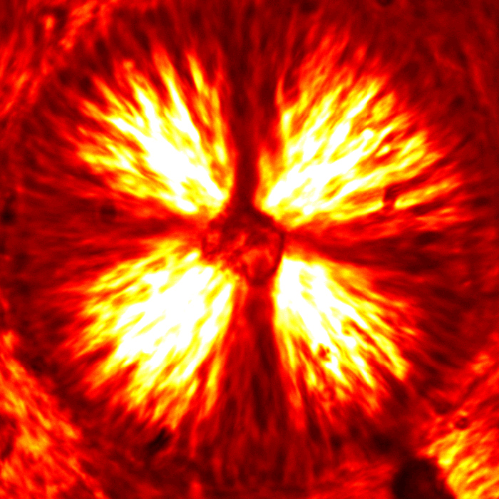
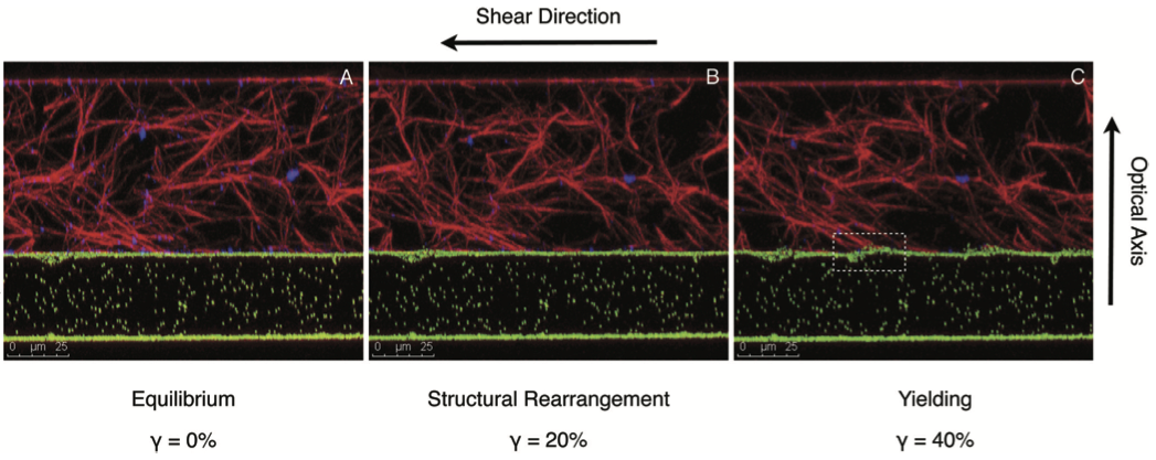
The fiber network structure of 0.2% type I rat tail tendon collagen
imaged using reflectance and fluorescence confocal microscopy
are shown below. Each movie shows a 25 μm traversal along
the optical axis.
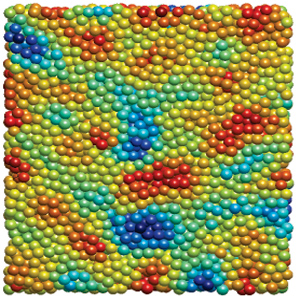
The movie below shows fluorescent microspheres embedded in a
polyacrylamide gel. The movie shows a 10 μm traversal along
the optical axis. Polyacrylamide is a clear non-fluorescent gel
with tunable rigidity. The fluorescent microspheres serve as
displacement markers.
Figure 1 shows a sketch of our two-layer system. The system consists of
a collagen fiber network layered over and adhered to polyacrylamide gel
embedded with fluorescent microspheres sandwiched between a rheometer
measuring tool and a coverslip. The confocal-rheometer coupling
allows us to image three-dimensional volumes of our system over time
while simultaneously applying shear stress.
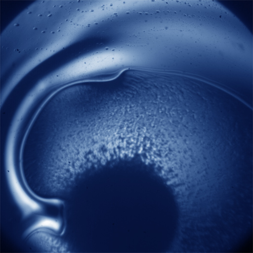
Movie 4 shows the collagen/polyacrylamide interface under shear
stress. Applied shear stress by the rheometer measuring tool at
the top of the collagen network transmits through the cross-linked
fibers reaching the interface inducing deformation at fiber/gel contact
points.
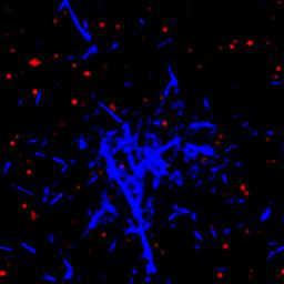
The microsphere positions are tracked in the three-dimensional volume
over time (an example shown in figure a) to obtain the non-uniform
deformation field (figure b). Once these displacements are known
we can determine the stress transmission at the interface (figure c)
and consequently analyze the corresponding network structure causing
the deformation (figure d).